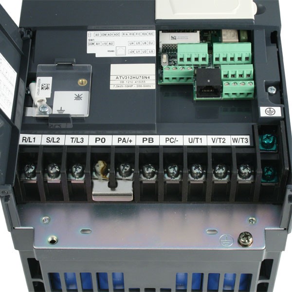
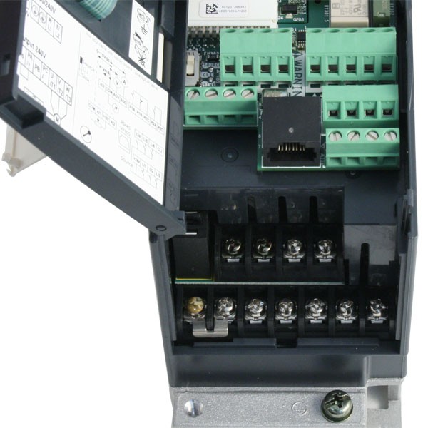
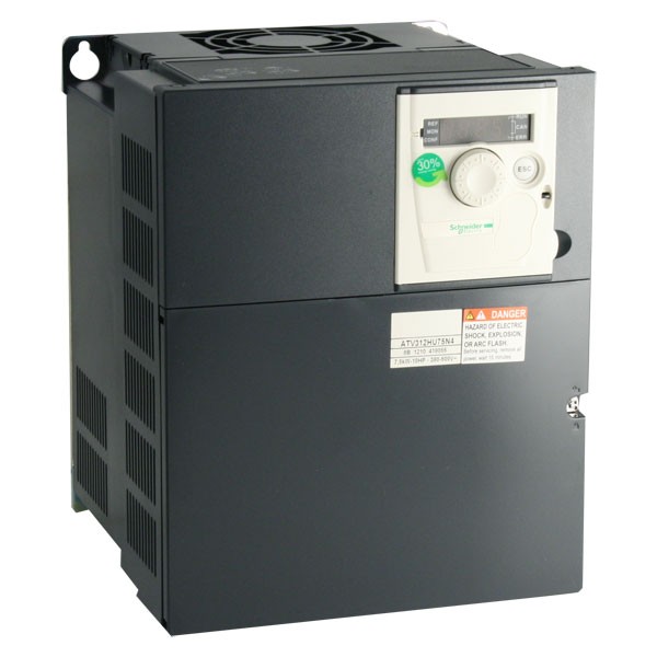
Retire el ATV del embalaje y compruebe que no presenta daños. .. Consulte el manual del programación (BBV) para una descripción completa del. Manual de programación Altivar® 06/ Contenido .. Altivar 31 (ATV31) es una familia de variadores de velocidad de ~ (c.a.) de frecuencia ajustable. Manual de programación. ATV Manual de programación Manual de programación · altivar-machine-atv ATV Manual de programación.
- Schneider Altivar 312 Installation Manual Diagram
- Schneider Altivar 312 Installation Manual Transmission
| Author: | Shahn Mataur |
| Country: | Comoros |
| Language: | English (Spanish) |
| Genre: | Relationship |
| Published (Last): | 12 October 2016 |
| Pages: | 422 |
| PDF File Size: | 17.41 Mb |
| ePub File Size: | 19.85 Mb |
| ISBN: | 727-5-89653-365-8 |
| Downloads: | 25559 |
| Price: | Free* [*Free Regsitration Required] |
| Uploader: | Zulkit |
Schneider Electric Altivar 312 Programming Manual Information below is designed to use single drive connected to single motor with a motor cable length less than 50 meters (164 ft). In any other case, consult the ATV312 installation manual (BBV46391) and programming manual (BBV46385) on www.schneider-electric.com. Check the delivery of the drive Page 5/10. The following Altivar 312 technical documents are available on the Schneider Electric website www.schneider-electric.com. Installation manual This manual describes how to install and wire the drive. Programming manual This manual describes the functions, parameters, and use of the drive terminal (integrated display terminal, optional graphic display.
Keep the control circuits away from the power circuits. Quick Start Progarmacion Quick Start describes how to wire and configure the drive to start motor quickly and simply for simple applications. Dimensions in mm width x height x depth.
3) ATV312 Guía de programación
Failure to follow these instructions can result in death, serious injury, or equipment damage. X and Y can be programmed from 0 to 20 mA, max. To measure the DC bus voltage: Do not place it close to heating elements. It is used to alert you to potential personal injury hazards. The temperature rise is controlled by a sensor in the power module. These manual describes the assembly, connection to the bus or network, signaling, diagnostics, and configuration of the communicationspecific parameters.
Simplified manual This manual is an extract from programming and installation manual.

Failure to follow these instructions will result in death or serious injury. Electrical equipment should be installed, operated, serviced, and maintained only by qualified personnel. This document is delivered with the drive.
Choose a suitable model integrating: Find the cause of the detected fault and correct it. The progrsmacion below gives the size according to the reference. These detected faults can also be reset by cycling power to the drive or by means of a logic input or control bit.
Spares and repairs Serviceable product: Variable speed drives for pumps with photovoltaic arrays. Restore power to the drive. Read and understand this manual before installing or operating the Altivar drive.

This diagram is for the standard ATV products. Variable speed drives for asynchronous motors.

Use the fuses recommended in the installation manual. Altivar V www. Please refer to the catalogue. In the event of a non resettable detected fault: Altivar – Schneider Electric Altivar Do not repair or operate the drive.
Altivar 312
Remember me Forgot password? Link 3 on the drive is then via the filter output cable. Please refer to installation and wiring details supplied with each board. Flow of air If you are installing the proframacion in enclosures, make provision for a flow of air at least equal to the value given in the table below for each drive.
Move the cable tag on the top left of the power terminals as illustrated below example: Mount the drive v Mount the drive in accordance with the instructions in this document see page Schneider Electric Altivar Drive – Grainger.
The size of the ground conductor must be selected in compliance with local and national codes. Size of the ground conductor must be selected in compliance with local and national codes. Use a permanent insulation monitor compatible with non-linear loads for example Merlin Gerin type XM Wait 15 minutes to allow the DC bus to discharge. The high frequency equipotential ground connection between the drive, motor, and cable shielding does not eliminate the need to connect the ground PE conductors green-yellow to the appropriate terminals on each unit.
Certain detected faults can be programmed for automatic restart after the cause has disappeared. The shield on the ungrounded end may be tied to ground with a capacitor for example: Please see the associated documentation pprogramacion the option cards for details.
Schneider Altivar 312 Installation Manual Diagram
Altivar –
The detected fault will no longer be present if it’s cause has been corrected. For switching frequencies above 4 kHz and derating conditions, please refer to the derating curves for guidelines. Isolated or impedance earthed neutral. Altivar – Sonepar.
If the installation includes several drives, provide one “residual current device” per drive. Altivar – Variateur de vitesse BBV Wire the drive see page 17 v Connect the motor, ensuring that its connections correspond to the voltage. If the DC bus capacitors do not discharge completely, contact your local Schneider Electric representative.
Variateurs de vitesse pour pompes For complete documentation, refer to www.
For control and speed reference circuits, we recommend using shielded twisted cables with a pitch of between 25 and 50 mm 1 and 2 in. Altivar – Sonepar www.
Most Related


The designer of any wiring diagram must take account of potential control channel Since it was first marketed, the Altivar ATV has been equipped with. You need product-specific knowledge. I would start with the manufacturer at Altivar - Documents and Downloads | Schneider Electric.
Installation manual RS OUR OFFER - Schneider Electric Altivar The Altivar drive is a frequency inverter for V three-phase asynchronous. Installation manual, to verify that the DC voltage is less than 42 V.
The . The standard schematic corresponds to the Modbus specification.
In any other case, consult the ATV installation and programming manual on See installation manual on wiringall.com for other thermal.wiring diagram is compatible with the macro-configuration, otherwise modify the diagram.
Schneider Altivar 312 Installation Manual Transmission
4 Check in the “DRIVE” menu that the factory parameters are compatible with those given on the motor rating plate.
5 Check in the “DRIVE” menu that the control mode is set to open loop (Ctr = SVC). 6 In the “DRIVE” menu, perform an auto tune.
The following overhead crane wiring diagram with atv pic has been published. You could grab this excellent image for your laptop, netbook or personal computer.
Additionally you can easily bookmark this page to you favorite social bookmarking sites. 4 BBV 04/ Important Information NOTICE Read these instructions carefully, and look at the equipment to become familiar with the device before trying to install, opera te, or maintain.
Jun 12, · Chapter 1 demonstrates how to connect the power wire to the ATV In any other case, consult the ATV in stallation and programming manual on wiringall.com Check your cables before connec ting the drive with .Solar pump inverter - Schneider Electric Altivar solarWiring Diagram Book | Schneider Electric